3D
Camera
References: - cameras · PyTorch3D - Pinhole Camera - Kornia
Camera Coordinate Systems
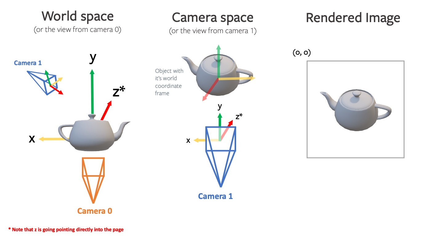
Camera Coordinate System: A reference frame that changes with camera position and orientation. In the camera coordinate system, the origin is at the camera position, with the Z-axis typically aligned with the camera's line of sight, and X and Y axes aligned with the camera's horizontal and vertical axes respectively.
World Coordinate System: A fixed, global reference frame used to describe object positions in a scene. In this coordinate system, each object's position is defined relative to a fixed point (world origin).
Intrinsic Matrix
Camera Intrinsic Matrix with Example in Python | by Neeraj Krishna | Towards Data Science
fxandfy: Focal lengths in pixels along the image plane's x and y axes. These reflect the lens magnification of the scene. Ideally, for square pixels,fxandfyshould be identical, but they may differ slightly due to lens distortion and manufacturing tolerances.cxandcy: Principal point coordinates, representing the image coordinate system origin's position on the image plane. Typically assumed to be at the image center but may be offset due to imprecise lens manufacturing and assembly.
The camera intrinsic matrix K is typically represented as:
Extrinsic Matrix
Camera Extrinsic Matrix with Example in Python | by Neeraj Krishna | Towards Data Science
Describes the camera's position and orientation in global space (world coordinate system):
- Rotation: The
3x3rotation matrix component enables object rotation around the origin. Rotations can be single-axis (around X, Y, or Z) or any combination thereof. - Translation: The
Tx,Ty,Tzelements enable object movement along each direction in 3D space.
In practice, a
4x4homogeneous transformation matrix is often used to handle both rotation and translation, simplifying calculations through a single matrix multiplication.
Homogeneous Coordinate Transformation Matrix
- \(R\) (Rotation Matrix): Describes how the camera coordinate system's basis vectors (forward, up, and right directions) are rotated relative to the world coordinate system.
- \(T\) (Translation Vector): Represents the camera coordinate system's origin (camera's optical center) position in the world coordinate system.
This matrix transforms points from camera coordinates to world coordinates through rotation by \(R\) followed by translation by \(T\).
For transforming \(P_w\) to \(P_c\), we use \(\mathbf{M}_{\mathrm{w2c}}\), which can be obtained through inverse transformation: \(\mathbf{M}_{\mathrm{w2c}}=\mathbf{M}_{\mathrm{c2w}}^{-1}\)
Trajectory files (
traj.txt) typically contain4x4transformation matrices per line:
Coordinate Transformation During Imaging
The projection of 3D world coordinates to 2D image plane involves:
- World to Camera Coordinates: Using homogeneous extrinsic matrix \(\mathbf{M}_\mathrm{w2c}=\begin{bmatrix}R&T\\0&1\end{bmatrix}\), transform \(P_w=(X_w,Y_w,Z_w,1)^T\) to \(\mathbf{P}_c=(X_c,Y_c,Z_c)^T\):
- Camera to Image Plane: Using intrinsic matrix \(K\), project \(\mathbf{P}_c=(X_c,Y_c,Z_c)^T\) to image plane pixel \(P_i=(u,v)\):